Hello everyone who want to vist my page.
I will post here some helpful information about my modyfications.
This is what I did is easy , require some basic electronic skils , but as Y ou can see, it change your gokart completly 🙂
Whart we need :
battery (I recommend you to use some 18650 cells , good fit under left side cover is 3S5P package, you can use any 12V with right capacity and size you need.
1 x 6PIn SMR 2.54 connector (male + female)
4m 0.25mm wires (green, yellow, red, black, white, orange colors)
JST 2.54 6 pin connectors male + female
Gear bracket for 15mm shaft SCSAW 15x35x12
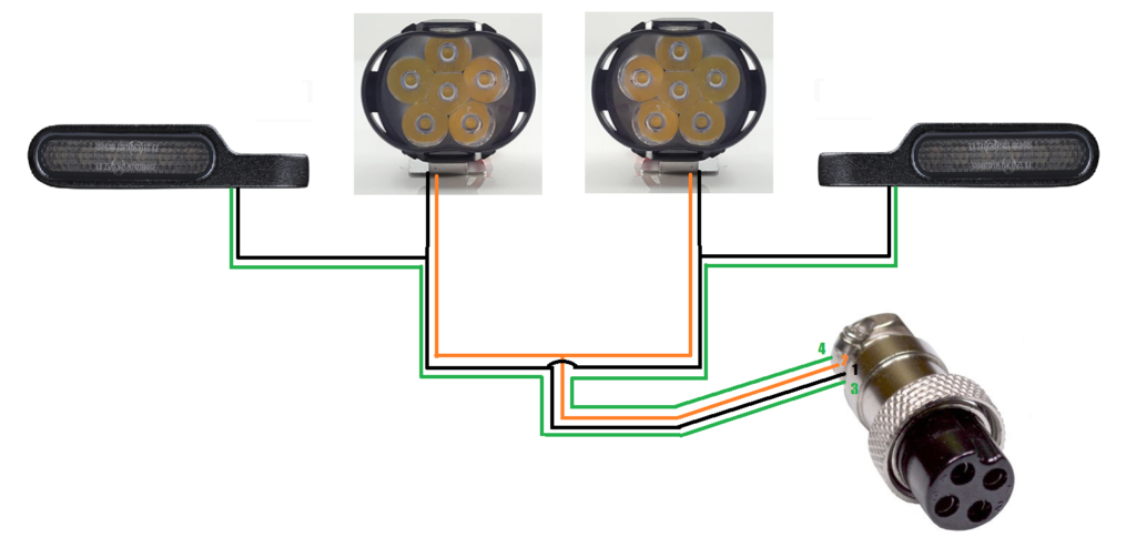
Step 1 - make a proper front lamps connection
They use commong GROUND , so all black wires you need connect toogethere
LAMPS wires also connect toogethere - because they will activate toogethere
only indicators need separate wires, because they will be ON indyvidual (left & right)
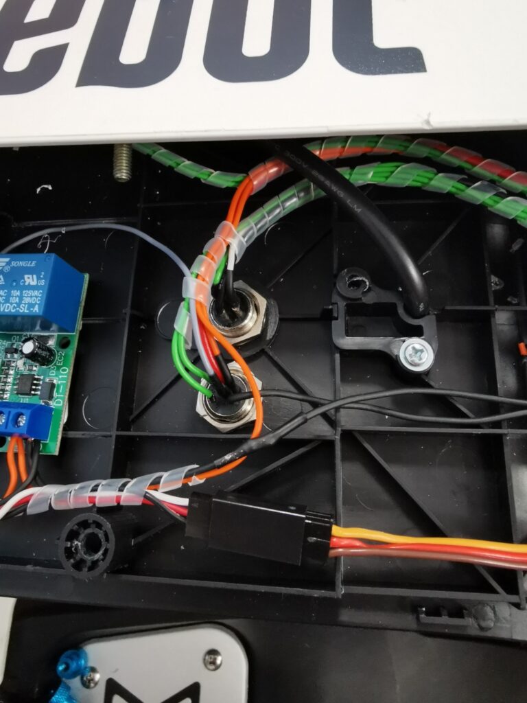
Step 2: Mount both GX16 connector in black plate (need remove first top cover)
one connector is for front lights , another one is for battery and back lights
keep cables color like i show on another picture
Green 1 = R Indicators
Green 2 L indicators
Black = GND
RED = Power 12v from battery
White = Power after swich for front lights and back lights
Orange = Read Brake lights
connect both GX connector and keep about 20cm left cables
remeber:
GX16-4 is going to front lamps
GX16-6 is going to battery andread lamps
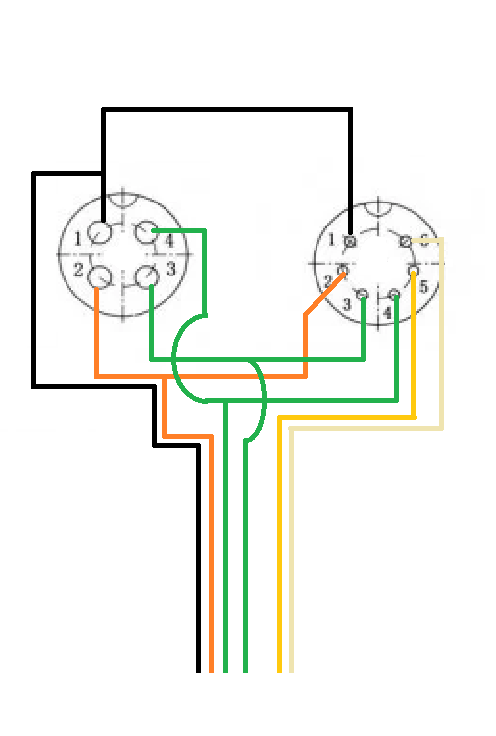
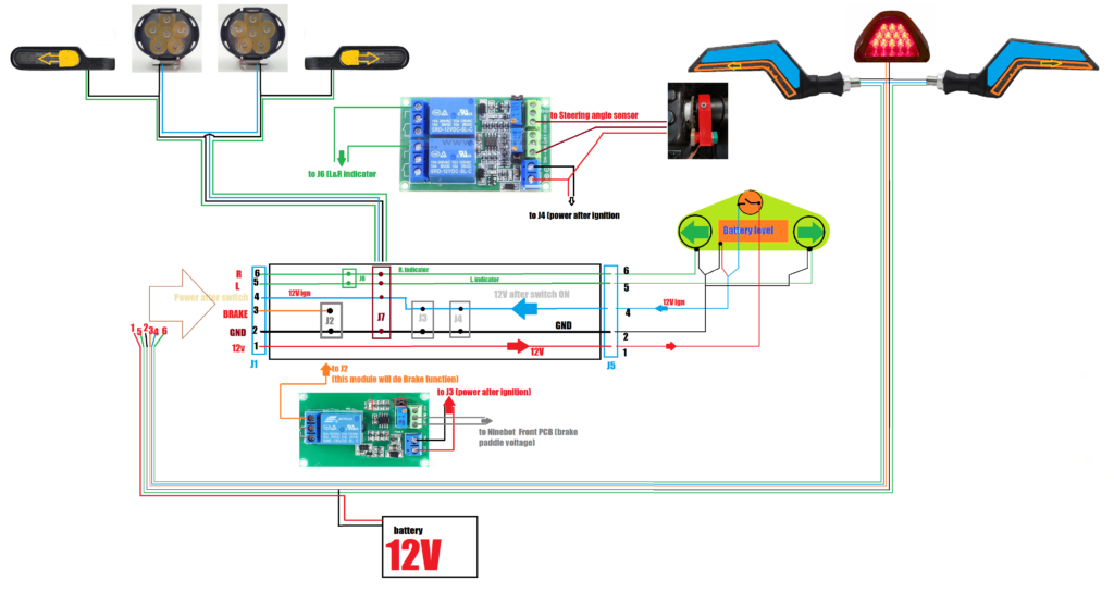
This is main connection diagram
Brake function:
When ypou apply brake - it simple provide voltage to Ninebot controler (top PCB)
If more brake = more voltage, if less brake = less voltage
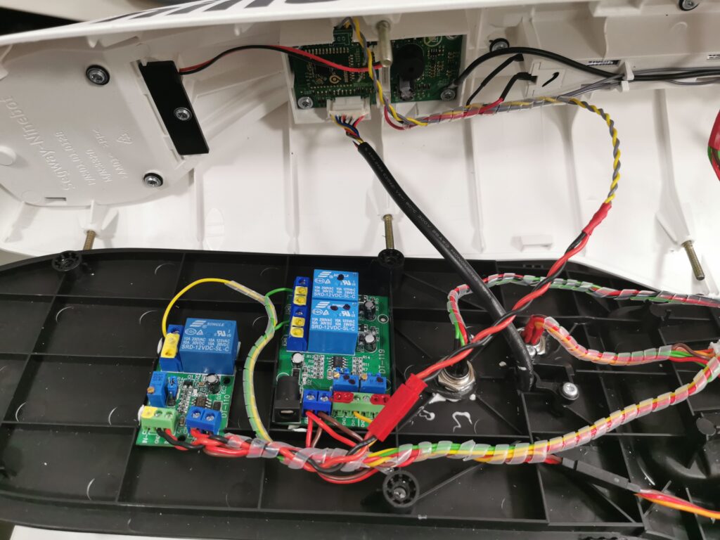
to activate simple "relay" function you can use "Voltage comparator"
it compare power voltage (our 12v) to voltage you aplly to activare brake
so is perfect for simple brake function
Steering angle sensor
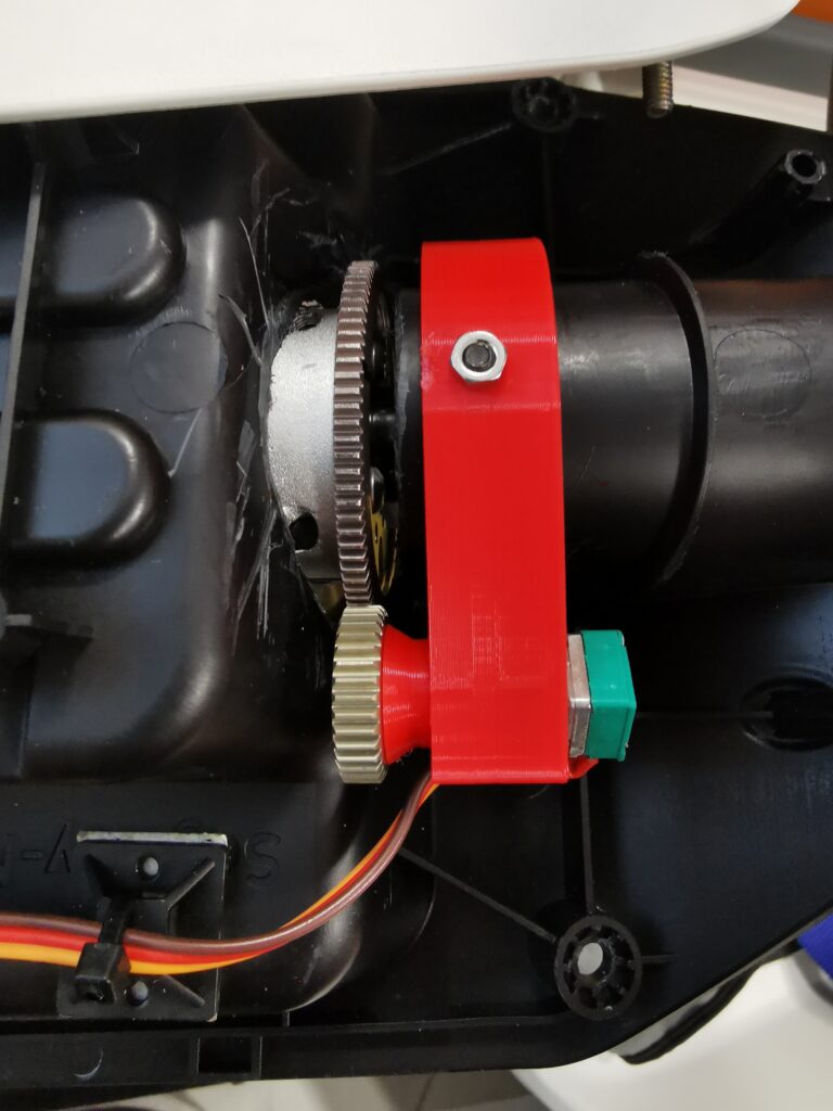
Angle sensor working similar like Brake Module
you use potentiometer - if you turn left - voltage between middle pin and left is getting less than between middle and right
If you turn right - voltage status between pins is change in reverse way
so our Dual Voltage comparator ompare that and do function 1 - swich relay 1 , or function 2 - switch relay 2
Because poteniometer can turn only 180-200 degrees , you need to use gear to do 1:2 or even higer ratio to not damage it